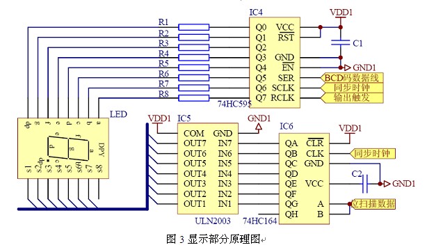
Fang Yan Wu Jianming (Shanghai Anke Rui Electric Co., Ltd., Shanghai Jiading 201801) Abstract : The design method and application of an intelligent temperature and humidity controller are introduced. The measurement and control of three-way temperature and humidity can be realized at the most; combined with RS485 bus technology and PC software, remote transmission of data and status information can be realized to meet the requirements of low-voltage power distribution. Intelligent and networked development needs. Design method and the application of intelligent controller based on STC89C58RD+&SHT11 for temperature and humidity Fang Yan, Wu Jianming Abstract :to ensure the electric equipment running in proper temperature and humidity condition is very important. The article brings forward a design method and the application of intelligent controller for temperature and humidity, which measures and controls temperature and humidity of up to three points. In Addition, this design method also consists of the functions of parameter setting and RS485 communications interface. 0 Introduction With the increasing scale of power systems and higher voltage levels, the reliability of power supply is also more stringent. The temperature and humidity of the power distribution equipment environment are important factors that affect the operation of the equipment. Excessive temperature will accelerate the aging of equipment and components, shorten its service life, and even cause direct damage to the equipment. Low temperature, humidity, condensation on the surface of the equipment may lead to accidents such as creepage and flashover. 1 Hardware circuit design 1.2 The specific circuit and principle of the hardware The core device microcontroller uses STC's STC89C58RD+ type single-chip microcomputer, it is an enhanced 8-bit machine compatible with 51 core, on-chip resources, anti-interference ability is outstanding. STC89C58RD+ (D version) supports 6 clocks/machine cycle, contains 32K bytes of user program space, on-chip integrated 1280 bytes of RAM, 16K bytes of EEPROM space; support ISP/IAP function, no special programmer; on-chip integrated look Door dog circuit and MAX810 dedicated reset circuit. Temperature parameter: parameter condition typical unit Resolution  0.01 °C Accuracy 0~60 ±1 °C Measuring range  -40 to 120 °C Humidity parameters: parameter condition typical unit Resolution  0.03 %RH Accuracy 20% to 80% ±3 %RH Measuring range  0~100 %RH The communication between the sensor and the CPU adopts the two-wire system, namely the DATA (data) line and CLK (synchronous clock pulse) line. When measuring three-way temperature and humidity, the connection circuit between the CPU and the sensor is shown in FIG. 2 . P1.0 and P1.1, P1.2 and P1.3, P1.4 and P1.5 in the CPU general I/O port are respectively connected to the three-way temperature and humidity sensor SHT11, among which P1.0, P1.2, P1 .4 respectively as the DATA (data) line of each communication, P1.1, P1.3, P1.5 respectively as the CLK (synchronous clock) line of each communication, DATA line needs to add a 10KΩ pull-up resistor to increase the signal To high level (refer to SHT11 data sheet for details). In actual use, the sensor and the controller (ie, dotted line in the figure) are connected by a shielded cable. After verification, the maximum communication distance between the CPU and the sensor is 10 meters. If the 74HC245 or other chip is used to increase the driving capability of the I/O port, it can increase the communication distance, but it will reduce the anti-jamming performance of the system and therefore it will not be adopted. The system uses LED digital tubes to display temperature and humidity values, and the interface is concise and clear. The temperature and humidity values ​​measured by the three-way sensors are displayed in a cyclic manner. There are 7 digital tubes in the display section, 4 of which are used to display the temperature (display range: -40.0 to 100.0), and the menus are displayed in the programming state. Parameters, 2 bits are used to display the humidity value (display range: 0 to 99), and 1 bit is used to display the number (1 to 3) of the corresponding sensor currently displayed or operated. The digital tube display adopts the dynamic scanning method, and its driving circuit is composed of integrated circuits 74HC595 and 74HC164. 74HC595 is an 8-bit serial input, parallel output (or serial output) shift register with output latch function for segment driver of the digital tube; 74HC164 serial input, parallel output function for scanning Display each digital tube, as shown in Figure 3. 2 software design method System software design includes the following four parts: The main program, measurement control module, display module and communication module. Program initialization includes configuring the SFR of the CPU, setting the initial state of the I/O port, reading the operating parameters from the EEPROM, and setting the reset time of the watchdog timer. It should be noted that generally only feeding the dog in the main program, the watchdog reset time has to be set longer than the longest waiting time possible in the measurement program. The following is a partial C language source code for the main program. 3 The product is applied to the temperature and humidity control in the power supply and distribution environment. Generally, the scheme shown in Figure 5 is adopted. Temperature and humidity information in a switchgear cabinet or box substation is collected by a temperature and humidity sensor, and a relay contact signal (disconnected or turned on) is output after processing by the controller, and the contact signal is then connected to a temperature and humidity control device (generally used In the power circuit of the heater or fan, it is used to control its operation or stop to realize the intelligent control of temperature and humidity. Technical Parameters index control target 1~3 Road Temperature and Humidity Features Warming Setting range: -10°C~10°C Cooling Setting range: 30°C~45°C Dehumidify Setting range: 75% to 90% Output Contacts Quantity Each set of temperature and humidity corresponds to 2 contacts capacity 250V/5A communication interface RS485 protocol Standard MODBUS-RTU Baud rate 1200, 2400, 4800, 9600, 19200 Auxiliary power AC/DC220V, allow 85~270V This type of temperature and humidity controller can control one, two or three temperature and humidity, each temperature and humidity sensor corresponding to a set of (two) relay output contacts, one of which is used to control the heater, to achieve temperature or dehumidification control Another contact is used to control the fan to achieve exhaust control. When a sensor or heater fails, the controller will send out an alarm signal. Aluminum alloy heater is the most commonly used temperature and humidity control equipment in the power supply and distribution system. The following is the relationship between the size of the environmental space and the choice of heater power for the reference of the reader. Environmental space size (m3) Heater power (W) ≤ 0.5 50 to 75 0.5 to 1 100 to 150 1 to 1.5 200 or so 1.5 to 2 250 or so 2 or more 300 or more The WHD intelligent temperature and humidity controller can transmit the measured temperature and humidity values ​​and various status information in the control system to the upper computer remotely through the RS485 communication interface. The remote machine management software realizes remote measurement and remote control, which meets the requirements of intelligentization and networking. Development requirements. 4 Conclusion This article describes an intelligent temperature and humidity controller design method and application, can achieve the maximum three-way temperature and humidity acquisition, control, and has programming parameters and RS485 (MODBUS-RTU) communications. Through practical verification, the WHD series products designed with reference to this method are easy to use by users in practical applications, and their temperature control and humidity control effects are significant. At the same time, the product's anti-electromagnetic interference performance is outstanding, for example, the anti-pulse group interference in the 5 kHz and 100 kHz frequency bands can reach three levels, and is suitable for use in electrical equipment with relatively poor electromagnetic environment. Article from: "Electrical Technology" 2006 the 10th period. references About the author: Fang Yan (1982-), Bachelor, major research direction for intelligent temperature and humidity control of power supply and distribution. Nut Brake Block,Lock Bolt Nut,Locking Nuts And Bolts,Metal Lock Nut ZHEJIANG HUAYE PLASTICS MACHINERY CO.,LTD , https://www.huaye-group.com
Keywords: SHT11, STC89C58RD+, Temperature and Humidity Control, RS485
(Shanghai Acrel Co., Ltd Jiading Shanghai 201801)
Keywords :temperature and humidity control SHT11 STC89C58RD+ RS485
Based on the above considerations, it is necessary to control the temperature and humidity in the power supply and distribution equipment such as medium and high voltage switch cabinets, box transformers, and terminal boxes. This article will introduce a WHD-based intelligent temperature and humidity controller design method to achieve maximum three-way temperature and humidity measurement and control; combined with RS485 bus technology and host computer software, remote data and status information can be achieved to meet the low voltage distribution Intelligent and networked development needs.
1.1 The overall idea of ​​the hardware design The hardware system is based on the single-chip microcomputer, and can be divided into five parts: power supply, temperature and humidity measurement, control output, human-machine dialogue and communication, as shown in Figure 1.
The power supply circuit converts the AC220V or other type of auxiliary power into the DC power required for the system operation. The one-chip computer compares and processes the temperature and humidity values ​​measured by the sensor, determines the working state of the output control part relay, and displays and sends the temperature and humidity values ​​and the working status information of the output control part. The man-machine conversation part has the key information input function, the user can set the working parameter of the system through the key programming according to the actual situation. 
The temperature and humidity were measured using a digital temperature and humidity sensor chip SHT11 developed by SENSIRION. The sensor can measure temperature and humidity at the same time and provide full-scale calibrated data output. Therefore, using this sensor can not only reduce the hardware cost, but also facilitate the whole machine test. Its technical parameters are shown in the following table: 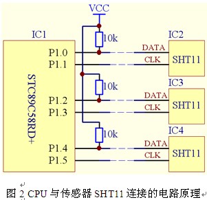
The system uses a relay or thyristor as the control output, the power supply part adopts the switching power supply scheme, and the communication part adopts the RS485 interface. For the specific circuit design, please refer to the relevant books, which will not be repeated here.
The main program completes the power-on or reset initialization, resets the watchdog, and inquires key information and other functions. The program design flow is shown in FIG. 
Void Main ()
{
WDT_CONTR = 0x00; // Close watchdog InitialEeprom(); // Read EEPROM
InitialIO();//Initialize I/O status InitialSFR();//Set SFR
InitialSHT11();//Initialize the sensor InitialComm ();//Initialize the communication port WDT_CONTR = 0x35;// Feed dog 1.25 seconds while(1)
{
WDT_CONTR = 0x35;
KeyScan();//keystroke query KeyProcess();// key information processing }
}
Communication and receiving/discharging processing, display and temperature and humidity measurement and control are realized by interrupts. The priority order is: serial communication interruption (highest) → display interruption → measurement control interruption (lowest).
The system communication adopts the standard MODBUS-RTU protocol, which facilitates the design of upper computer management software and is used with other network instrumentation networks to achieve complete monitoring of the power supply and distribution system. 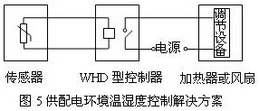
The general technical specifications of the WHD intelligent temperature and humidity controller are as follows:
The controller can also set the hysteresis of the temperature and humidity control, that is, the difference between the start condition and the stop condition of the adjustment device. As shown in FIG. 6 , taking the heating up temperature as an example, when the ambient temperature drops below the preset “heat start temperatureâ€, the controller outputs a contact conduction signal, the heater works, and the ambient temperature gradually rises; when the ambient temperature rises to When the “heat stop temperature†is exceeded, the controller outputs a contact open signal and the heater stops heating. According to experience, the amount of hysteresis is generally set within the range of 4 to 10 (°C or RH%). 
[1] Application Guide for Digital Temperature and Humidity Sensors SHT1X/SHT7X, SENSIRION, Switzerland, 2005
[2] STC89C51RC/RD+ Series Microcontroller User's Guide, Hongjing Technology, 2006
[3] Dai Jia, Dai Weiheng 51 single-chip C language application program design, 2006